Learning By Doing In C Part 4 - Back to the BIOS?
Intro
I’ve always been interested in DOS. A 16 bit operating system from a simpler time.
DOS relied on BIOS interrupts, an abstraction layer for interfacing with hardware through the BIOS. Want to use the keyboard? Print to the screen? Read sectors on a disk? Just load up values in some registers, invoke an interrupt using a CPU instruction and let the BIOS take care of the rest.
mov ah, 0x0e    ; function number = 0Eh : Display Character
mov al, '!'     ; AL = code of character to display
int 0x10        ; call INT 10h, BIOS video service
The BIOS would initialise all the hardware at boot, from printers to VGA displays. It will then set up blocks of code to interact with them and interrupt vectors to use them. After that it will move the instruction pointer to ‘0x7C00’ and leave you on your own, able to use the APIs that the BIOS has set up for you.
‘0x7C00’ isn’t just a magic number. It’s the position where code in your boot sector gets loaded into. Exactly 512 bytes, the size of a sector. As you can see, that is not even barely enough for any kind of serious program, bootloader or operating system. Luckily the BIOS provides an API/Interrupt to read sectors from disks into memory anyway, I wont use these though, I like restrictions.
16 bit is nice, but for anyone wanting to address more than 64KiB of memory without extreme effort should look elsewhere. Unfortunately, modern x86_64 has to live with the legacy cruft that comes with backwards compatibility. Just booted your x86 CPU? Even if your CPU has support for 64 bits, it boots in 16 to ensure compatibility with (extremely) old systems. It has to now be taken from 16 bit “Real Mode”, to 32 bit “Protected Mode”, to finally 64 bit “Long Mode” to use it’s full capabilities.
You following? Time to write some 16 bit assembly targeting the boot sector.
‘jmp $’
The dollar sign in NASM simply means the address of current instruction. Jumping to the instruction that caused you to jump in the first place just means an infinite loop, this is used to halt the CPU so that it doesn’t keep going on into memory and trying to ’execute’ random data.
jmp $
This isn’t enough though, it wouldn’t run. There is more to unpack here.
| |
Line one tells NASM that these instructions are 16 bit, if that was not there, instructions would be wider byte wise than they should be.
Remember how I said that all code gets loaded into the memory address ‘0x7C00’? If we didn’t take this into account addressesing any kind of memory would be completely off.
‘org 0x7C00’ lets NASM know to offset all memory accesses by that amount. Without it NASM would assume that this code gets loaded into the beginning of memory, 0x0, and thus addresses in code will be completely off.
Lines 6 to 7 are used to place two bytes exactly at the end of the sector using compiler trickery.
All it does it pad the binary with zeros to get to the 510 byte mark, then filling the rest in with bytes 0x55 and 0xAA. Those two bytes hint to the BIOS that this sector is a bootable one and will mark it to be loaded at the address I wrote about above, 0x7C00. This is the boot signature.
This setup finally allows an x86 compatible CPU to finally start executing our code.
$ nasm -f bin main.asm -o boot.bin
$ qemu-system-i386 boot.bin
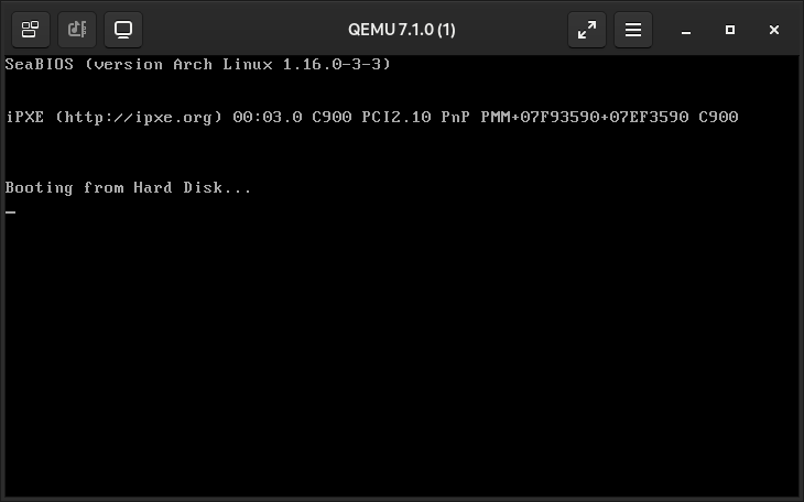
It does nothing. Perfect!
It’ll take a little more to get text up on the screen. Don’t worry though, the BIOS has got our back.
It’s only an interrupt away. Which one do we call? I’ve showed it above, ‘int 10h’.
Instructions on how to use a certain BIOS interrupt are avaliable online if you are willing to search for them. Wikipedia is a good choice.
‘call puts’
mov ax, string
call puts
jmp $
; NOTE: 10h and 0x10 are the same
; thing. hex numbers were often
; denoted with a 'h' back then
; AX: pointer to null terminated string
puts:
mov bx, ax
mov ah, 0x0E ; set AH to 0x0E.
; when int 10h is
; activated, display
; a character
.while:
mov al, byte [bx] ; deref character
test al, al ; is 'al' zero?
je .exit ; null character (0),
; end of string
int 0x10 ; write out character
; in AL register
inc bx ; incremement pointer
; to next char in str
jmp .while ; continue looping
.exit
ret
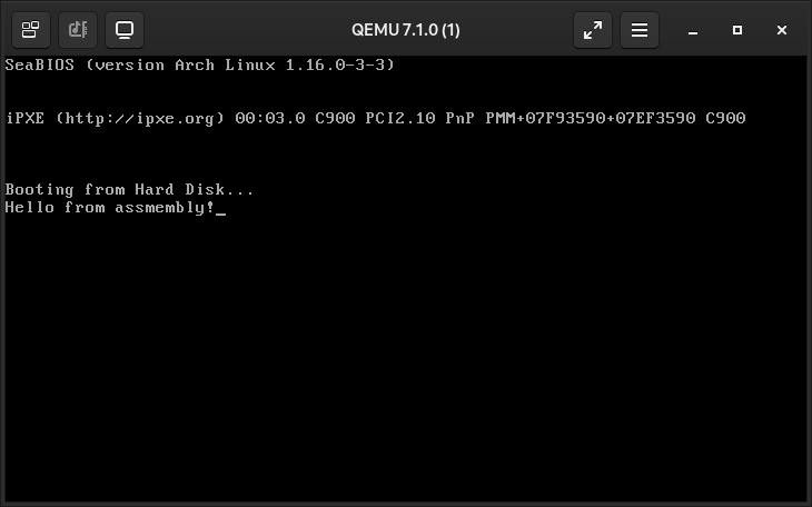
string: db 'Hello from assmembly!', 0
BITS         General Purpose Registers
  16 |   AX,    BX,    CX,    DX
        /  \   /  \   /  \   /  \
   8 | AL  AH BL  BH CL  CH DL  DH

                    Indexing Registers
  16 | SI, DI

                       Stack Registers
  16 | SP, BP

                      Segment Pointers
  16 | CS, DS, SS, ES

                   Instruction Pointer
  16 | IP
The 16 bit general purpose registers, AX, BX, CX and DX, can all have their 8 bit low and high counterparts accessed by changing the X to either a H (for high) or an L (for low).
Print a single character,
INT 10h with AH = 0x0E:
   AL = Character,
   BH = Page Number,
   BL = Color (only in graphic mode)
Take a good look at the code on the right and the register specification above. String lengths above 255 will cause the rest to be placed on a different page. Just ignore that for now…
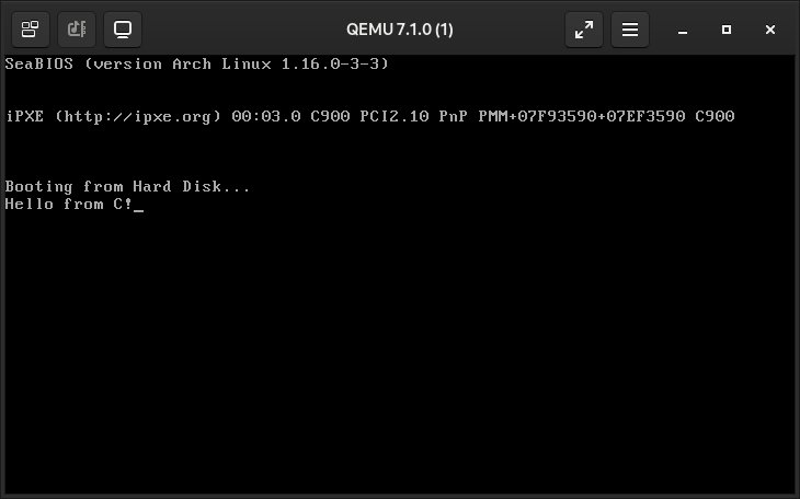
Assembly is tedious, I know you came here for C. Time to write some 16 bit C code!
16 Bit C. This counts as embedded, right?
Getting C to start up with constraints like these is quite involved. First, you need a flat binary. One stripped of debug information and no sections (.data, .text, .bss), this can be done in the linker. You would also need some kind of bootstrapping code written in assembly to invoke the main C function. I’ll give you the rundown.
’entry.asm’ is our setup code calling into the main function. It clears all the segment registers by first clearing out the AX register, and assigning it to all of them. Loading an immediate value into segment registers is simply not possible, you must use general purpose one to set the value first.
It then moves the stack pointer to the top of our 4KiB pointer set in the linker. Why the top? In x86, the stack grows downwards. Allocating memory on the stack would require you to subtract from the stack pointer.
BITS 16
section .text

extern __stack_top
extern main

xor ax, ax
mov es, ax
mov ds, ax
mov ss, ax
mov ds, ax
mov sp, __stack_top
cld
call main
jmp $
The linker script, it outlines how to set up the final 512 byte binary with the compiled code it is given. No need to do ‘org 0x7C00’ or place the boot signature, it’s handled in here.
SECTIONS
{
  . = 0x7C00;
  .text : {
    entry.o(.text) /* entry.asm */
    *(.text)       /* rest of C code */
    *(.data)
    *(.rodata)
    *(.bss)
  }
  /* place boot signature */
  .sig : AT(ADDR(.text) + 512 - 2)
  {
      SHORT(0xaa55);
  }
  . = . + 0x1000;
  __stack_top = .;
}
With all that setup done you are free to write whatever you want in C, except for … BIOS interrupts. Yeah, you still need assembly for that. At least you can do it inline right inside your C code, except it’s in AT&T syntax. Not that C inline assembly is confusing already. It’s fine, just do some reading.
| |
I will not give a full explaination of inline assembly (because even I don’t know it to a full extent), I will just explain lines 3 to 5.
| |
When using the ‘volatile’ keyword, similar to variable declarations, it indicates to the compiler that the assembly should never be optimised out if reachable.
Inline assembly follows this syntax on the right. Marking registers as outputs and inputs along with specifying their uses are mostly for assisting the compiler in optimisation.
The inline assembly above opts to skip the outputs, going for the input list. Placing a register in the input also assumes it is in the clobbered registers list.
The clobbered registers list is so the compiler can save their contents before making your the assembly call, as putting them in this list tells the compiler that their contents will be overwritten.
asm ( "instructions"
    : output operands     (optional)
    : input operands      (optional)
    : clobbered registers (optional)
);
These one character strings here have meaning, along with the parentheses, they both make an inline assembly ‘constraint’ for the compiler to follow.
The character string relates to a register and the parentheses, what value it should be when the assembly is called. How the AX register is assigned is tricky to get your head around at first.
"a"(0x0E00 | *s++), "b"(0)
- ‘a’ refers to AX
- ‘b’ refers to BX
- ‘c’ refers to CX
- ’d’ refers to DX
- ‘S’ refers to SI
- ‘D’ refers to DI
Remember how above I wrote about printing a single character using a BIOS interrupt? AH had to be equal to 0x0E and the lower 8 bits, the AL register, to be set to the ASCII character code.
Since we are setting the entire 16 bits of the AX register, we can use a bitwise or to set the upper bits (the ones that should be in AH) to it’s required value when combined with the 8 bit character code (that should be in AL).
The BX register should simply be 0, to avoid drawing characters on a different page. I hope you got all that!
Don’t worry, inline assembly doesn’t get much harder than this.
I wanna draw things to the screen!
Sure, the BIOS has got you covered.
mov ah, 0
mov al, 13h
int 10h
void int13h() {
    asm volatile (
        "mov $0x0013, %%ax\n"
        "int $0x10\n"
        ::: "ax"
    );
}
This will throw you into a VGA video mode with a screen screen of resolution 320 by 200, inclucing a whopping 256 colours. This is 8 bit colour, not 32 bit colour RGBA that everyone is used to nowadays. However, you can set any of the 256 colours to whatever you want, specified in a colour palette. The default one is kind of all over the place, but we won’t need to replace anytime soon.
One more thing. There is a BIOS interrupt to write a pixel to the screen, spoiler alert, BIOS interrupts are kind of fucking slow. No really. Want to fill the screen with a single colour? An interrupt for each pixel is 320 times 200, 64000. After 64 thousand painstakingly slow interrupts, the screen will be filled, but 5 seconds would have passed. That is way too slow for any kind of game loop or screen drawing.
However, after the video mode has been set, just peek into memory at ‘0xA0000’ and flip some bytes. This is where video memory is located. In this video mode (13h) setting one byte to any colour value, 0 to 255, will reflect that colour in the palette and place it in on the display. Easy right?
‘0xA0000’ seems a little high, 640KiBs high. 16 bits can only represent 65536 different numbers, 64KiB.
You do remember me writing that you can only address up to 64KiBs of memory right? We would need at a 20 bit number to reach memory addresses in the 640KiBs.
The fact that I am still sitting here writing this would tell you otherwise, of course Intel would have done something about this.
You can only access 64kb? Just multiply that by 16!
x86 Segmented Addressing
The four 16 bit segment registers I talked about earlier, CS, DS, SS, ES, these are used as an offset to address more memory. When trying to access memory higher than 64KiB, you have to address relative to a segment register.
The base address, bounded from zero to 64KiB, is offsetted by the value in a segment register multiplied by 16.
This allows for memory accesses as high as a megabyte, at 64KiB increments at a time.
You are essentially taking a 64KiB slice into a 1MiB pie with segmentation.
mov ah, 0
mov al, 13h ; video mode 13h
int 10h ; 320 by 200, 256 colours
mov ax, (0xA0000 / 16) ; moving an
mov es, ax ; immediate value into a
; segment register isn't
; possible (ask intel)
mov bx, ( 100 * 320 + 160 ) ; center
mov [es:bx ], byte 3
; mov [es * 16 + bx], byte 3
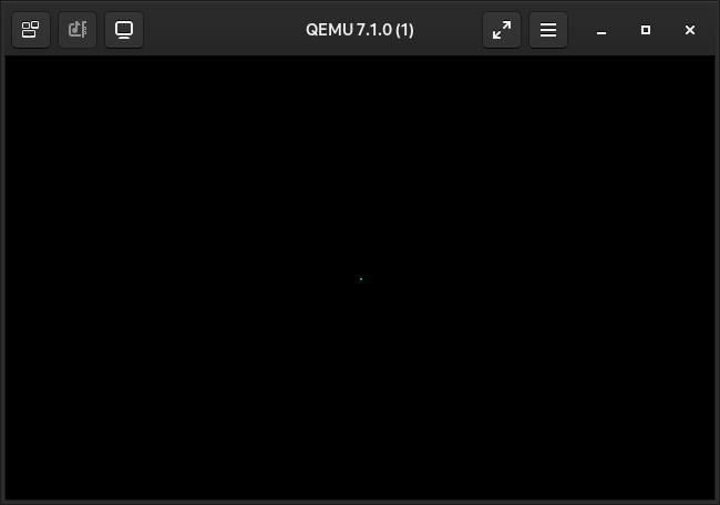
jmp $
A single tiny blue pixel.
Some instructions and core registers use some segments implicitly.
The SI index register is an offset from the DS data segment, the DI index register is offset by the ES extra segment.
The instruction pointer, IP, is offset from the CS code segment. The SP and BP, the stack pointer and base pointer respectively, are offset from the SS stack segment.
- CS - The code segment
- DS - The data segment
- SS - The stack segment
- ES - The extra segment
The extra segment, however, is exactly what the name implies. It is used by some string operations though.
All compilers have no idea about segmentation as most of the time they don’t even take it into account.
With good reason, x86 segmented addressing became completely obsolete with the advent of higher bit processors. In 32 or 64 bit modes all segments are usually set to zero to avoid confusion. In 16 bit, having all segments set to zero is called the ’tiny memory model’. 64KiBs is perfectly fine for any program, I mean, on most systems the space allotted for your programs stack is 8KiBs. The tiny memory model is really pleasant to work with, until you need to access some memory in higher ranges such as VRAM, then you will need some kind of segmentation.
Time to plot some pixels.
A VGA Rectangle
typedef unsigned char u8;   // instead of using an int value, which is usually
typedef unsigned short u16; // 32 bits on all most architectures, in 16 bit it
typedef short i16;          // is not. you should explicit with 16 bit datatypes.

#define VGA_WIDTH 320
#define VGA_HEIGHT 200

void segment_to_vram(void)
{
    asm volatile (
        "mov   $0xA000, %%ax\n"
        "mov   %%ax, %%es\n"
        ::: "ax"                    // "clobbered registers", save these registers
    );                              // before running this inline asm
}

void vga_pixel(i16 x, i16 y, u8 c)
{
    if (x >= 0 && x < VGA_WIDTH && y >= 0 && y < VGA_HEIGHT) {
        u16 pos = y * 320 + x;
        asm volatile (
            "mov %%al, %%es:(%%bx)" // AT&T syntax for segmented memory access
            :: "b"(pos), "a"(c)     // reg inputs, assumed to be clobbered anyway
        );
    }
}

void int13h(void)
{
    asm volatile (
        "mov $0x0013, %%ax\n"
        "int $0x10\n"
        ::: "ax"
    );
}

void main(void)
{
    int13h();                         // enter 256 colour VGA mode
    segment_to_vram();                // set extra segment

    u8 c = 0;                         // u8s roll over at 255 back to 0

    i16 x, y;
    for (y = 50; y < 150; y++) {
        for (x = 80; x < 240; x++) {
            vga_pixel(x, y, c++);     // draw a blue box
        }
    }
}
Easy. Lets check the size…
$ objcopy -O binary boot.elf boot.bin
$ wc -c boot.bin
176 boot.bin
…that’s pretty big for a tiny program like that.
Thirty percent out of the five hundred and twelve bytes we have access to. It’s time to talk about space optimisations.
Compiler Assumptions.
Here is what we’re doing already. These are the flags passed to GCC. You won’t need to know or understand all of them, that’s my job. What you should know is that without them, GCC will assume that this code will be ran on a 64 bit CPU with a ton of cool modern features like position indepentent code or a functioning libc.
CC := gcc                                # gcc produces smaller code than clang

CFLAGS := -ggdb3 -m16 -ffreestanding -fno-PIE -nostartfiles -nostdlib -std=gnu99 \
    -Wall -Wextra -fomit-frame-pointer -fwrapv -fno-strict-aliasing \
    -fno-stack-protector -fno-pic -Wno-unused-function -Os

                                         # -m16   -> generate 16 bit instructions
                                         # -ggdb3 -> debug symbols for gdb
                                         # -Os    -> strictly optimise for size

# boot.bin is a flat binary to be passed straight into qemu
# boot.elf contains all the debug symbols exempt from boot.bin

boot.bin boot.elf:
    $(CC) -o main.o $(CFLAGS) -c $(CFILES)
Besides the flags passed to GCC, there is so much more we can do to make the binary smaller.
The first thing to do is to handle the infinite halt in C instead of assembly.
[BITS 16]
section .text

global mystart
extern __stack_top
extern main

xor ax, ax
mov es, ax
mov ds, ax
mov ss, ax
mov ds, ax
mov sp, __stack_top
cld
- call main
- jmp $
+ jmp main
void main(void)
{
    int13h();
    segment_to_vram();

    u8 c = 0;
    i16 x, y;
    for (y = 50; y < 150; y++) {
        for (x = 80; x < 240; x++) {
            vga_pixel(x, y, c++);
        }
    }

    for(;;); // <-- this is new
}
The infinite loop in the main function will translate to the same ‘jmp $’ we removed in the assembly, this does nothing! Not exactly…
GCC assumes that the main function will always return to it’s caller, so GCC adds instructions that preserve the callers stack frame.
These are all redundant instructions. There is no stack frame set up in assembly that needs to be preserved.
Take a look at the disassembly. Keep in mind that the 32 bit registers in the disassembly are just for show, objdump doesn’t know that this is a 16 bit binary.
Disassembly of section .text.startup:

<main>:
    push   edi
    push   esi
    mov    esi,0x32
    push   ebx
    calld  7c45 <int13h>
    calld  7c11 <segment_to_vram>
    mov    al,0xa0
    mov    edx,esi
    mov    ebx,0x50
    imul   eax,edx
    mov    edi,eax
    lea    eax,[edi+ebx*1+0x70]
    movzx  eax,al
    push   eax
    push   esi
    push   ebx
    inc    ebx
    calld  7c18 <vga_pixel>
    add    esp,0xc
    cmp    ebx,0xf0
    jne    7c76 <main+0x2a>
    inc    esi
    cmp    esi,0x96
    jne    7c64 <main+0x18>
    jmp    7ca6 <main+0x5a>
Disassembly of section .text.startup:

<main>:
    push   edi
    push   esi
    mov    esi,0x32
    push   ebx
    calld  7c47 <int13h>
    calld  7c13 <segment_to_vram>
    mov    al,0xa0
    mov    edx,esi
    mov    ebx,0x50
    imul   eax,edx
    mov    edi,eax
    lea    eax,[edi+ebx*1+0x70]
    movzx  eax,al
    push   eax
    push   esi
    push   ebx
    inc    ebx
    calld  7c1a <vga_pixel>
    add    esp,0xc
    cmp    ebx,0xf0
    jne    7c78 <main+0x2a>
    inc    esi
    cmp    esi,0x96
    jne    7c66 <main+0x18>
    pop    ebx
    pop    esi
    pop    edi
    retd
That’s a four instruction save! The three pop instructions for the stack frame and the return instruction. About 10 bytes were shaved off from the final binary.
That’s quite minor though, I know something that’ll completely cut the binary in half.
More Assumptions.
GCC assumes that all functions have the possibility to be called from outside the current context (the C file), so GCC will limit all optimisations to the functions body only.
This means…
- No function inlining
- No dead function elimination
- No precomputation
- No skipping branches
But there isn’t any outside context. I am not writing a library. This is not an API.
A C compiler has to assumes that all C functions may be linked and called outside the C file later on.
This is a program for the CPU and nothing else. Functions are just dead weight, or size, if they are never called.
Look at this function call.
vga_pixel(26, 382, 4);
If GCC knew that the argument ‘y’ would not satisfy the if statement as it is larger than the VGA display’s height, it could just skip it.
Even if the arguments were legal, like this…
vga_pixel(280, 103, 4);
…the branch could be skipped and the multiplication and addition computed beforehand.
But you can’t just edit a function to bend to the one instance it was called, right?
Compiler Copy Pasting
Instead of calling a function, just copy paste it’s body to where it was called. This is called function inlining and allows for some amazing optimisations.
void main(void)
{
    vga_pixel(280, 103, 4);
}
void main(void)
{
    asm volatile (
        "mov %%al, %%es:(%%bx)"
        :: "b"(33240), "a"(4)
    );
}
If you are optimising for size, which is critical for the space constraints of the boot sector, function inlining very necessary. If the arguments are known at compile time and the function’s code is to be inlined, many optimisations can take place.
Constant variables can be calculated when compiling, branches can be removed, if statements skipped, and entire blocks of unneeded instructions can be omitted.
Disassembly with inlining
Disassembly of section .text.startup:

<main>:
    push   ebx
    mov    ebx,0xffff81d8
    calld  7c18 <int13h>
    calld  7c11 <segment_to_vram>
    mov    al,0x4
    mov    BYTE PTR es:[bx],al
    jmp    7c38 <main+0x19>
The second line, after removing two byte padding…
mov bx, 0x81d8
…that’s 33240 in hex. It precomputed the value after inlining the function!
Since the vga_pixel function was not called elsewhere and was dead weight (code), it was eliminated. Dead code elimination is it’s actual term.
The size without inlining pixel function is 107 bytes, after inlining it was 62 bytes. Inlining it cuts the amount of instructions in (almost) half!
Disassembly without inlining
Disassembly of section .text:

<vga_pixel>:
    push   ebx
    mov    ecx,DWORD PTR [esp+0x8]
    mov    edx,DWORD PTR [esp+0xc]
    mov    al,BYTE PTR [esp+0x10]
    cmp    cx,0x13f
    ja     7c41 <vga_pixel+0x29>
    cmp    dx,0xc7
    ja     7c41 <vga_pixel+0x29>
    imul   bx,dx,0x140
    add    ebx,ecx
    mov    BYTE PTR es:[bx],al
    pop    ebx
    retd

Disassembly of section .text.startup:

<main>:
    calld  7c45 <int13h>
    calld  7c11 <segment_to_vram>
    pushd  0x4
    pushd  0x67
    pushd  0x118
    calld  7c18 <vga_pixel>
    add    esp,0xc
    jmp    7c6e <main+0x22>
The thing is, I had to force GCC to not inline the function to get the output above. Sometimes when optimising it is actually not worth the space and time to small function, the overhead is not worth it.
#define NOINLINE __attribute__ ((__noinline__))

void NOINLINE vga_pixel(i16 x, i16 y, u8 c);
So, how do you actually do function inlining?
The static keyword.
By defining a function as static to the file it is in, GCC can utilise techniques like function inlining and even eliminate the function entirely if it is not called. All C compilers have to assume that all functions will be later linked and called in other contexes outside the current C file, making a function static forces them to make different decisions. A static function will not be ’exported’.
Keep in mind that the ‘static’ keyword does not automatically allow a C compiler to start inlining like crazy, all it does is tell it the scope of the function, allowing it to take further assumptions.
You actually don’t need to make a function static to inline it. Placing the C keyword ‘inline’ on a function declaration is also applicable.
static void my_function();
inline void tiny_function();
As a rule of thumb, mark every function except the main function as static. The main function cannot be static anyway as it must be avaliable to be called from the entry assembly file.
Now that all of the boring terminology and assembly time to write something cool!
The Mandelbrot Set
Based on some code from an earlier GUI project with SDL (which also took pseudocode from Wikipedia), this section calculates the mandelbrot set.
#define MAX_ITERATIONS 255

static f80 x_scale = 4.00;
static f80 y_scale = 4.00;
static f80 x_shift = 0.0;
static f80 y_shift = 0.0;

/* when a global variable is static GCC can also assume
   that it will not be modified outside the file.
   if that global variable does not change, GCC can just
   copy paste (inline) the contents to where it is used  */

static u16 calculate_mandel_naive(f80 _x, f80 _y) {
    f80 x = 0, y = 0;
    u16 iteration = 0;
    while (x*x + y*y <= 2*2 && iteration < MAX_ITERATIONS)
    {
        f80 xtemp = x*x - y*y + _x;
        y = 2*x*y + _y;
        x = xtemp;
        iteration++;
    }
    return iteration;
}

/* takes up 64 extra bytes compared to the naive implementation.
   it seems to not be worth the space, as there is barely any speedup */
static u16 calculate_mandel_mul_optimised(f80 _x, f80 _y) {
    f80 x2 = 0, y2 = 0, x = 0, y = 0;
    u16 iterations = 0;

    while (x2 + y2 <= 4 && iterations < MAX_ITERATIONS)
    {
        y = 2 * x * y + _y;
        x = x2 - y2 + _x;
        x2 = x * x;
        y2 = y * y;

        iterations++;
    }
    return iterations;
}

static void draw_mandel(void) {
    const f80 mandelX_offset = (x_scale + x_scale) / VGA_WIDTH;
    const f80 mandelY_offset = (y_scale + y_scale) / VGA_HEIGHT;

    f80 mandelX = -x_scale + x_shift;
    f80 mandelY = -y_scale + y_shift;

    i16 offset = 0;
    for (i16 y = 0; y < VGA_HEIGHT; y++){
        for (i16 x = 0; x < VGA_WIDTH; x++){
            u16 a = calculate_mandel_naive(mandelX, mandelY);
            asm volatile (
                "mov %0, %%es:(%%bx)\n"
                ::"r"(a), "b"(offset)   // "r" in a means any register and is
            );                          // accessed with %0 (zeroth constraint)
            offset++;
            mandelX += mandelX_offset;
        }
        mandelX = -x_scale + x_shift;
        mandelY += mandelY_offset;
    }
}
Wait, floats in 16 bit? What’s an ‘f80’?
The x87 FPU
In the 1980s, the original x86 CPUs had a completely separate math coprocessor that handled floating point math. It was sold as an extension to your computer and was typically bought if you needed to speed up floating point calculations done in software.
The first coprocessor was called the 8087, since then all FPUs (floating point units) have been called a ‘x87’.
There are 8 floating point ‘registers’ on a x87, ‘ST(0)’ to ‘ST(7)’. They are each 80 bits wide.
You heard me, 80 bits wide.
Not 32, not 64, 80 bits wide. Intel were really ahead of the game with that one, just that idea though, the x87 floating point instruction set fucking sucks. I haven’t done much floating point programming, either opting for newer stuff like all the SIMD registers or letting the compiler work it out for me.
I put the word registers in quotes back there, because they work like a stack. Each x87 instruction will generally pop the first two items off the stack and push the answer back on to the top of the stack. All values also must be taken from memory, so you cannot move between general registers and floating point ones.
All this legacy stuff is now integrated inside the CPU, including newer technology like SIMD and higher (than 80?) floating point arithmetic.
Wanna use them? Define these types.
typedef long double f80; // will use x87
typedef __float80 f80; // gcc extension
I opt to use a long double because vscode uses the ‘clangd’ C and C++ language server, it gives me squiggly lines even when I specify a GNU standard in it’s arguments.
int a = sizeof(long double);
Just setting a global variable, it will appear in the dissassembly on the right.
00007c14 <a>:
    7c14:       0c 00 00 00
Stores 12 in big endian representation, why big endian? I don’t know. Anyway, 96 bits is a pretty round number, being a multiple of 32 bits (4 bytes).
(Back To) The Mandelbrot Set
void main(void) {
    int13h();

    for (;;)
    {
        draw_mandel();
        x_scale *= 0.4;
        y_scale *= 0.4;
        int16h();
    }

    for(;;) asm("hlt");
}
static void int16h()
{
    asm volatile ("mov   $0x00, %%ah\n"
                  "int   $0x16\n"
                  ::: "ah");
}
This function just calls a interrupt at hex sixteen, specifically one wait and return keypress. We don’t use it’s output, it’s just for waiting.
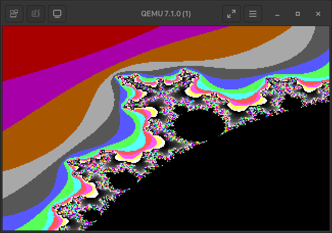
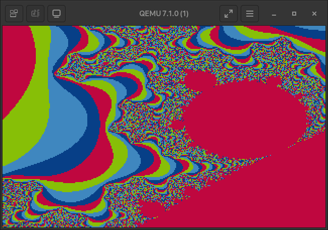
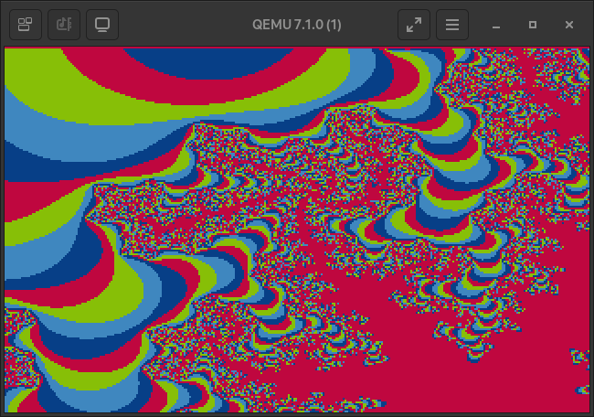
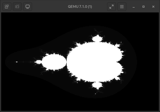
Anyway, here it is! Pretty nice right?
The default VGA palatte is very colourful, but only up to the 104th colour.
The bulbs of the mandelbrot fractal map to the 256th colour, black, because they are bounded by the max iterations allowed in the calculation function. Further away from the fractal’s bulbs the iteration value that is used to map to the palatte drops of exponentially. A you zoom further in, most map to the darker sections of the palette.
Let’s change it!

Changing The Colour Palette
VGA offers us 6 bits per color channel, not the 8 bits per channel that we’re used to.
Most games that utilised a VGA colour palatte, like the original DOOM, contained their own colour palette textures that could be fed straight into VGA controller. We don’t have 62.5kb to store any of that, it has to be generated at runtime.
To communicate with legacy hardware directly, like the VGA controller, the ‘in’ and ‘out’ instructions are used to receive and send data over specific ports. I used the word ’legacy’ here because modern technology like PCI Express require way more setup, instead of the hardcoded hardware addresses of legacy devices.
Dividing by four maps the 0 to 255 eight bit range to a 0 to 64 size bit range acceptable in a VGA palette. Without it, like every unsigned number, it would simply wrap around.
static inline void outp(u16 port, u8 val)
{
    asm volatile ( "outb %0, %1" : : "a"(val), "Nd"(port) );
}

#define PALETTE_INDEX 0x03c8
#define PALETTE_DATA 0x03c9

static void write_palette(){
    outp(PALETTE_INDEX, 0);

    for (u16 i = 0; i < 256; i++)
    {
        outp(PALETTE_DATA, i / 4); // RED
        outp(PALETTE_DATA, i / 4); // GREEN
        outp(PALETTE_DATA, i / 4); // BLUE
    }
}
This generates a nice black to white linear gradient.
Now there is one last problem, how do we make the screen render instantly instead of pixel by pixel?
Double Buffering
Using the VGA memory to write each mandelbrot calculation will place each pixel on the screen as soon as it’s written, it’s probably best to show it all at once.
This is where fitting all the code inside that 512 byte sector gets tight.
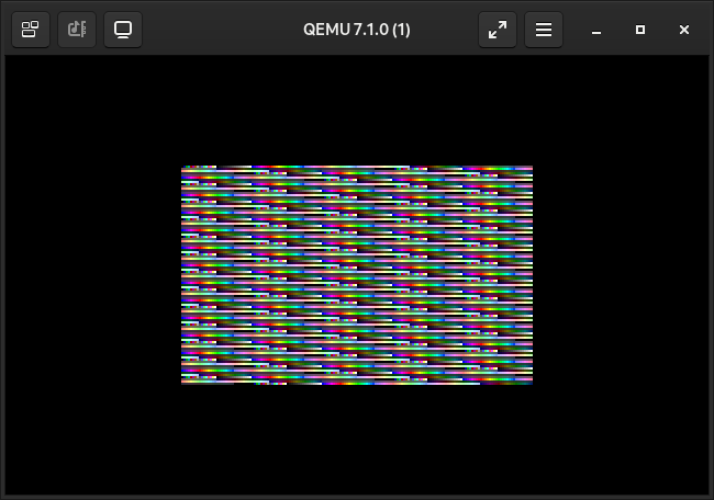
Something like this!
(Created using a modulo based palette that wraps around a black to write gradient.)
See how it displays instantly? No tearing at all. It even includes loading text!
Double buffering is simple. Instead of writing straight to VRAM, you write to a seperate buffer (hence the double in double buffering). When you want the user to see something, you copy the data from the buffer back to VRAM. Copying takes less time than waiting for the entire thing to render anyway.
How it’s accomplished is by simply swapping the segments and copying across. Take a look at the new main function.
void main(void) {
    int13h();
    write_palette();

    for (;;)
    {
        segment_to_buffer();   // set ES extra segment to our buffer

        draw_mandel();

        wait_for_vblank();     // wait for the VGA blanking period, right
                               // before a screen redraw. this gives us the
                               // most time to issue a lengthy copy

        segment_to_vram();     // set ES extra segment to VRAM
        segment_memcpy();      // copy across buffer and VRAM segments

        scale *= 0.4;          // moved both X and Y scale to a single variable
                               // 60 bytes of free space! (savings from less FPU
                               // instructions and storing the variables itself)

        int16h();
        display("loading..."); // same print function from before, just
                               // calling a int to reset cursor to (0, 0)
    }

    for(;;);
}
All VGA monitors have a VBLANK or vertical blanking interval interval. It’s the time between the final visible line of a frame or field and the beginning of the first visible line of the next frame. It’s done like this.
#define VGA_INPUT_STATUS 0x03DA
#define VGA_BLANK 0x8

static void wait_for_vblank()
{
    while ( (inp(VGA_INPUT_STATUS) & VGA_BLANK));
    while (!(inp(VGA_INPUT_STATUS) & VGA_BLANK));
}
Initiating the copy during this time is optimal.
The memory layout for real mode is defined in the x86 spec.
Addresses ‘0x00007E00’ to ‘0x0007FFFF’ contains exactly 480.5KiBs of conventional, free use memory. This is where I store the second buffer.
static void segment_to_buffer()
{
    asm volatile (
        "mov   $0x07E0, %%ax\n"
        "mov   %%ax, %%es\n"
        ::: "ax"
    );
}
static void segment_to_vram()
{
    asm volatile (
        "mov   $0xA000, %%ax\n"
        "mov   %%ax, %%es\n"
        ::: "ax"
    );
}
After calling the function that sets the extra segment to the second buffer, the mandelbrot code will draw directly to that.
But how would you copy between segments? Wouldn’t that require constant segment switching?
Read a value, switch segments, write value, switch back. Thankfully, there are better ways.
Intel created instructions for working with strings, not very useful in modern CPUs, kind of critical for my uses.
I use the ‘MOVS’ or ‘move string’ insruction. They work on the assumption that a string would be stored in the extra segment, being copied to the data segment. It can be looped when prefixed with ‘REP’, repeating and decrementing CX until the value in the CX register is zero.
Remember what I wrote before? The SI register is offset by the DS data segment and the DI register is offset from the ES extra segment.
The SI and the DI register keep their own offsets for the ‘MOVS’ instruction, I set them both to zero since we are copying from the start of each segment.
The D after the ‘MOVS’ tells the CPU to copy in double word sizes. On most architectures a word size is usually 16 bits, a double word is 32.
The more I can copy at once the better.
static void segment_memcpy()
{
    asm volatile (
        "mov   $0x07E00, %%ax\n"
        "mov   %%ax, %%ds\n"
        ::: "ax"
    );

    // DS:SI into ES:DI
    // buffer into vram

    asm volatile (
        "mov $0, %%si\n"
        "mov $0, %%di\n"
        "mov $16000, %%cx\n"
        "rep movsd\n"
        ::: "ax", "cx", "si", "di"
    );

    asm volatile (
        "mov   $0x0, %%ax\n"
        "mov   %%ax, %%ds\n"
        ::: "ax"
    );
}
Closing Notes (And Images!)
You know, this was the first time i’ve breached the one thousand line count on a post.
My interest with writing code for wacky archtectectures with weird constraints is growing. I also just love going low level with old technology. One day I’ll revisit this, maybe next time I’ll read a couple more sectors off the disk. It’s been really fun writing all this code, as always it’s avaliable on Gitea and Github.
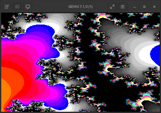
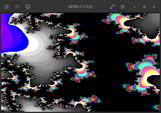
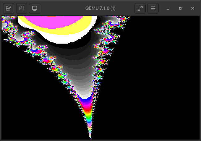
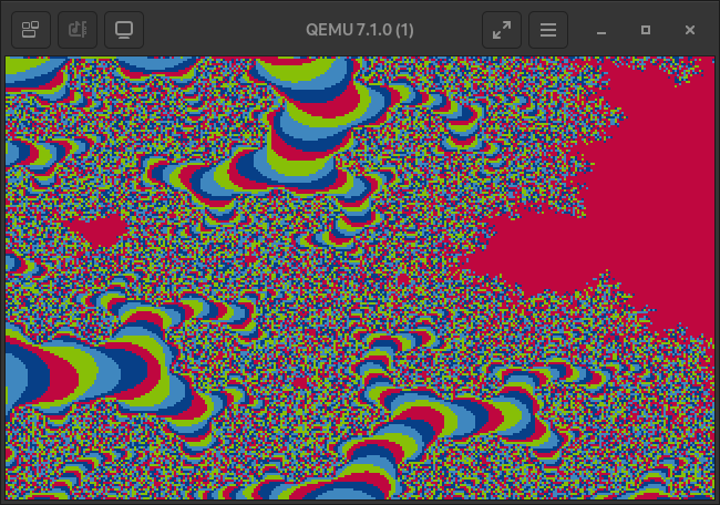
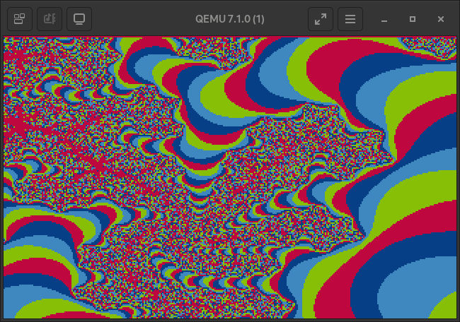
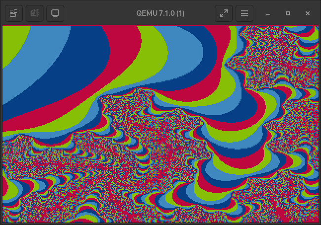
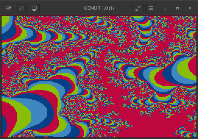
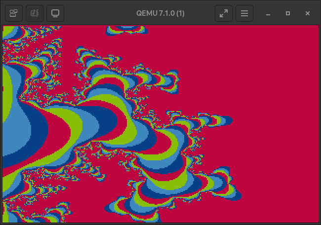
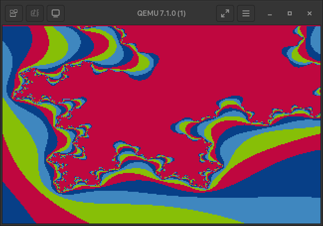
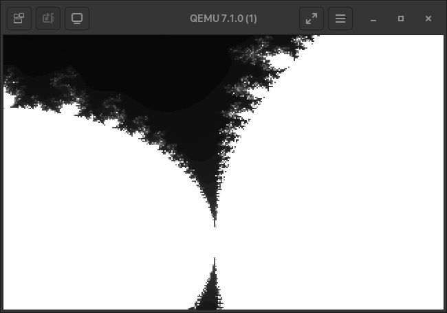
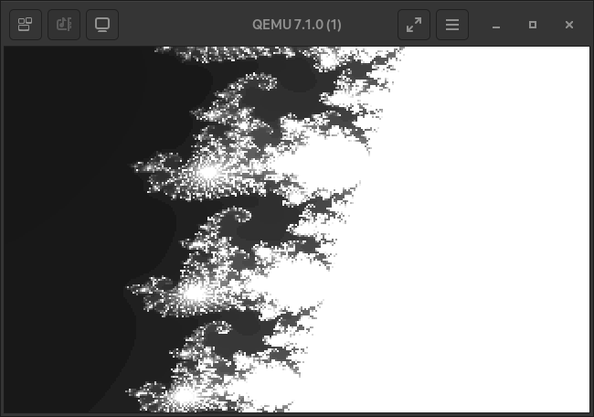
Take some more images as a parting gift.
Goodbye!